
Arduino Uno R3 & First Project
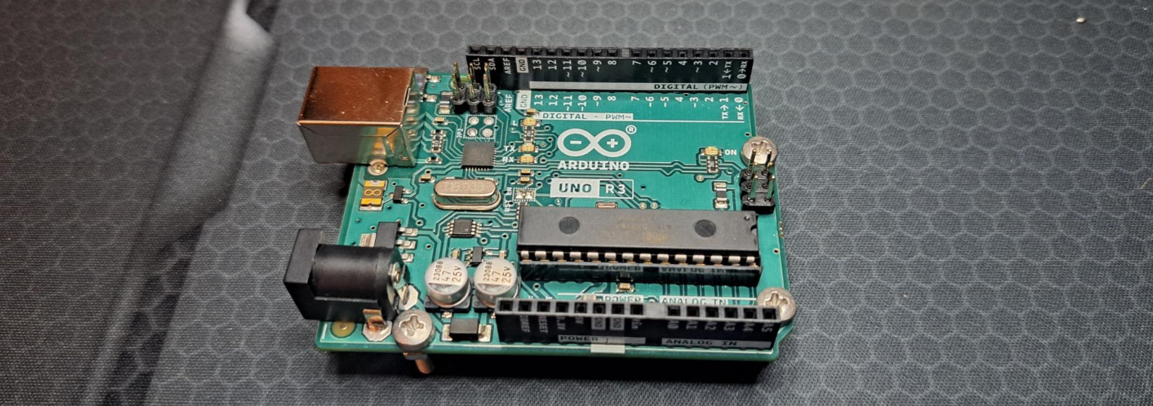
I'm Matt, a new apprentice at Red Crow Lab. Today I'm sharing a blog post about the Arduino UNO. The Arduino UNO is a microcontroller board based on the ATmega328P. It has 14 digital input/output pins (of which 6 can be used as PWM outputs), 6 analog inputs, a 16 MHz ceramic resonator, a USB connection, a power jack, and an ICSP header.
Board Specs
Name: A000066 Arduino UNO R3
USB Connector: USB-type b
Microcontroller: ATmega328p
Pins:
- Built in LED: 13
- Digital I/O Pins: 14
- Analog Input Pins: 6
- PWM Pins: 6
Communication:
- UART | Yes
- I2C | Yes
- SPI | Yes
Power:
- I/O Voltage:
- Input Voltage (nominal)
- DC Current Per I/O Pin
- Power Supply Connector
Clock Speed:
- Main Processor: ATmega328P 16 MHz
- USB-Serial Processor: ATmega16U2 16MHz
Memory:
- ATmega328P: 2KB SRAM, 32KB FLASH, 1KB EEPROM
Physical Dimensions:
| Weight | 25 g |
|---|---|
| Width | 53.4 mm |
| Length | 68.6 mm |
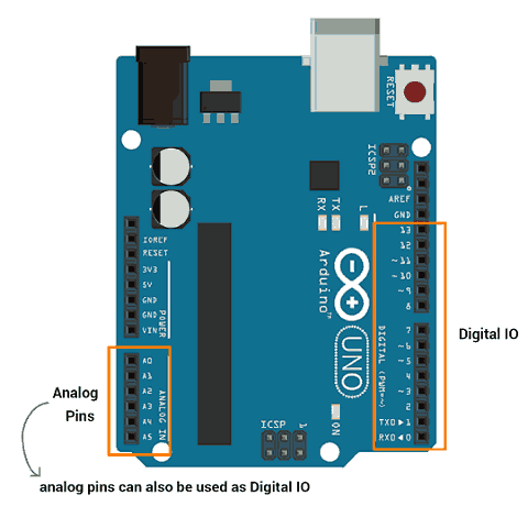
Pinout Diagram:
Using the Arduino Uno to make a working Servo, on a Breadboard.
In this walkthrough, I'll how you how to program the Arduino Uno using a Potentiometer on a Breadboard.
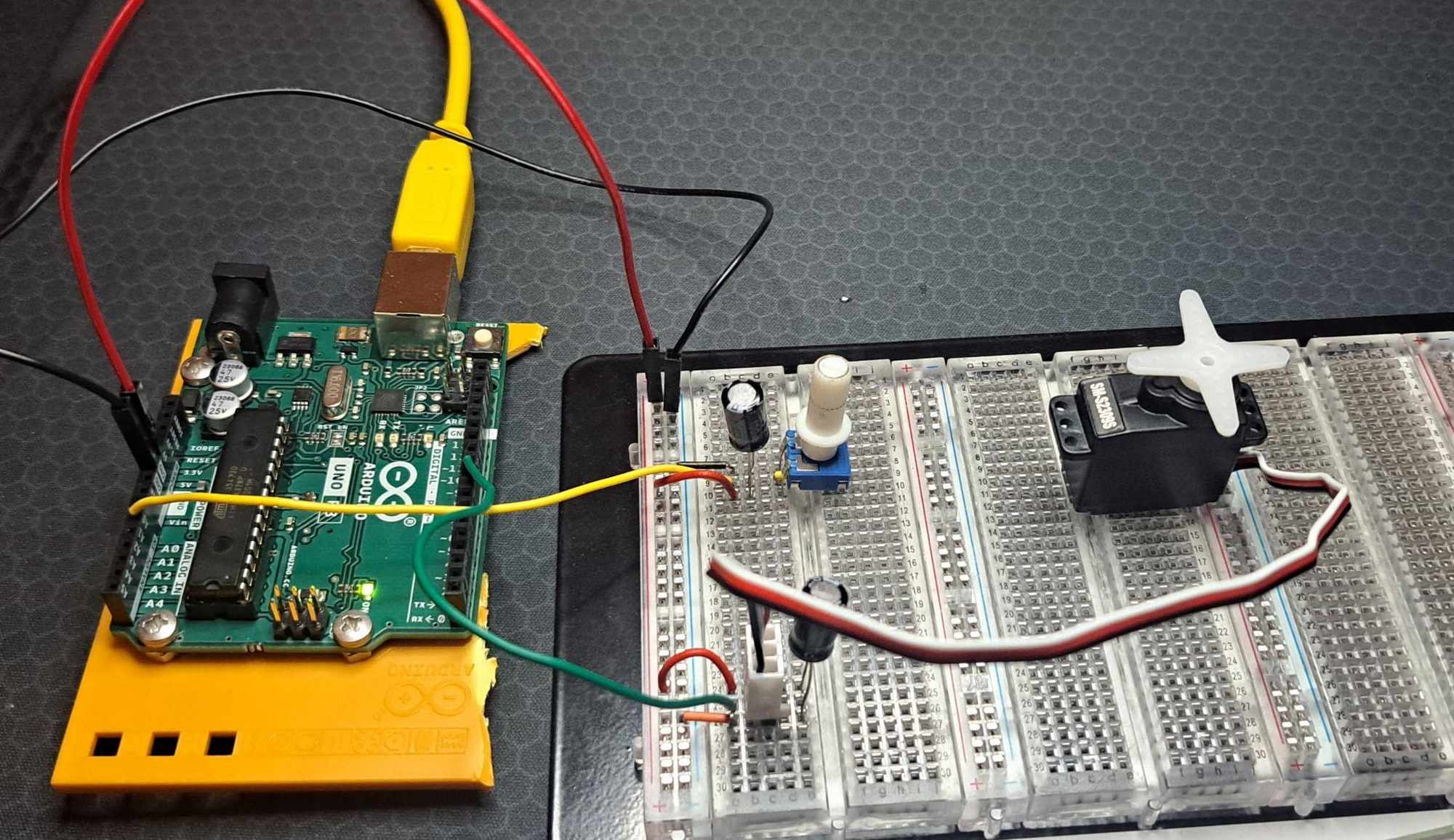
Material's Needed:
- 2x 100uf Capacitors
- 1x Potentiometer
- 1x Servo Motor
- 1x Arduino Uno
Start by attaching the potentiometer to the breadboard, connect one side to 5v (red wire), and the other to ground (black wire).
The potentiometer acts as a type of voltage divider, As you turn the knob, you change the ratio of the voltage between the middles pin and power. You can read this change by an analog input on the Arduino Uno. Connect the middle pin to analog pin (0). This will control the position of your servo motor. ( *see pinout diagram for reference )
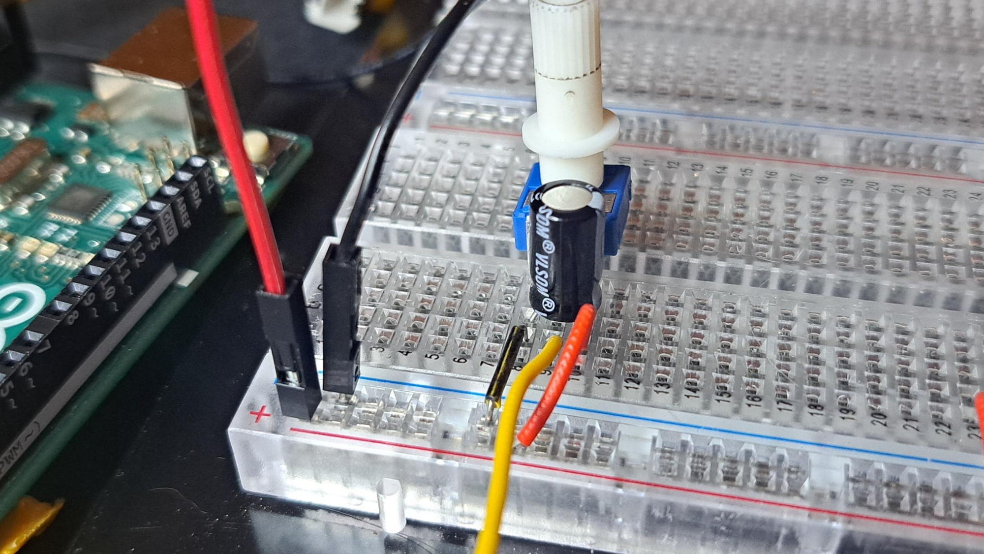
When a servo motor starts to move initially, it draws more current than if it were already in motion. This will cause a dip in the voltage on your board. By placing a 100uf capacitor across the power and ground right next to the male headers of the potentiometer as shown in the image.
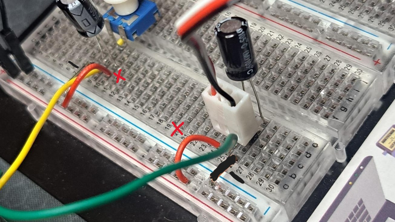
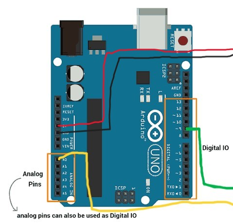
Now plug in the male-pin headers of your motor to 3 different rows on your board, then connect the red to 5v, the black to ground on you Breadboard. The white wire is control and it'll receive the information coming from the Arduino Uno. Connect it through the Digital (9) input on the Arduino using the Green wire. ( use picture below for reference ).
Arduino Uno Servo Setup Pinout diagram
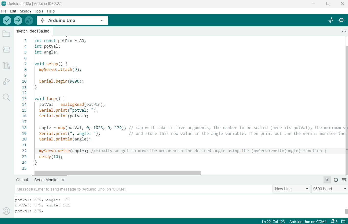
Now with everything hooked lets move onto the coding. Open the Arduino IDE and enter the following code:
#include <Servo.h>
Servo myServo; // Create a servo object to control the servo
const int potPin = A0; // Assign the potentiometer to analog pin A0
int potVal; // Variable to store the value from the potentiometer
int angle; // Variable to store the servo position
void setup() {
myServo.attach(9); // Attaches the servo on pin 9
Serial.begin(9600); // Begin serial communication at 9600 baud
}
void loop() {
potVal = analogRead(potPin); // Read the value of the potentiometer
Serial.print("potVal: ");
Serial.print(potVal);
angle = map(potVal, 0, 1023, 0, 179); // Map the pot value to a range of 0 to 179 degrees
Serial.print(", angle: ");
Serial.println(angle);
myServo.write(angle); // Set the servo position according to the mapped value
delay(10); // Wait for 10 milliseconds
}
It should end up looking something like this:
This code sets up a named constant 'potPin' to read the value from the potentiometer and control the servo's angle, and we'll be telling it which pin. In this case 'A0', the Arduino's analog A0 output, ( pot being Potentiometer )
The #include <Servo.h> line imports the Servo library, allowing us to call Servo from the library. Then declare myServo as a Servo class (this will be the actual "object" we'll be calling).
Bellow, store the value coming from the potentiometer, as well as the servo's position. To do that go ahead and use the, int potVal; and int angle; functions.
In the setup() function we'll attach myServo to digital pin 9 and set the serial communication between the Arduino and the computer at '9600' bits per second.
Moving onto the loop() function in this program, you'll want read the pots value coming from the pin (using the Serial.Read function as shown above). Then you'll print it onto the serial monitor with Serial.print aswell as, Serial.print(potval);.
Now we'll want to map the pot value to a range using 'map'. The map function scales numbers for you automatically, and it takes in 5 arguments, the number to be scaled (here its potVal), the minimum value of the input (0), the maximum value of input (1023), the minimum value of the output (0), and the maximum value of the output (179).
Finish by printing the angle and the angle's value to the serial with, Serial.print(", angle: "); & Serial.println(angle);
with that, now we can actually move the servo using, myServo.write(angle); and add a delay(10); (10miliseconds). This will change the servo's position according to the mapped value the potentiometer sends by you turning it.
Now with the code verified and uploaded with the Checkmark & Arrow at the top left of you IDE software.
Turing your potentiometer should now display the potVal and Angle's change with the pots change in voltage.
With that your servo motor should be able to successfully turn back and for 180* based on the angle you turn the potentiometer on your breadboard.
My next post will be on using the Saleae Logic Analyzer to read a signal from an Arduino Uno.
Matt