
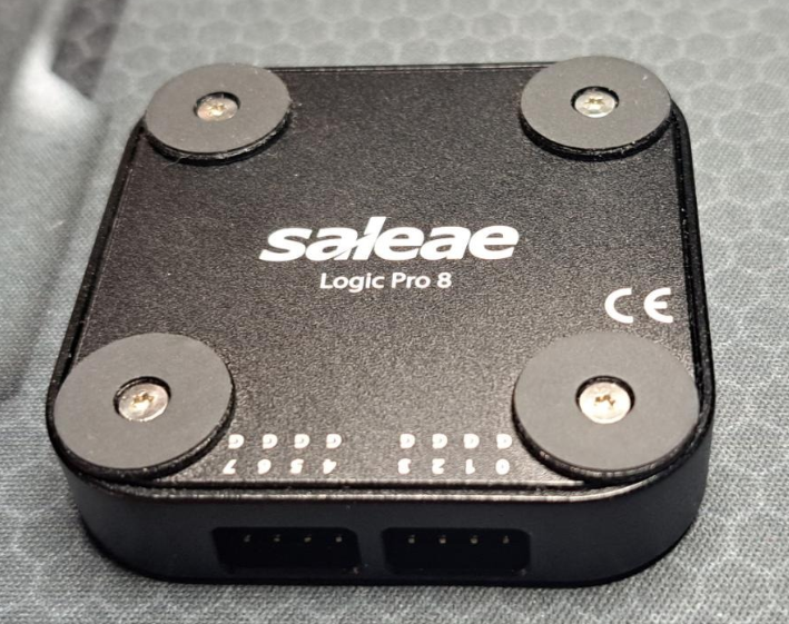
Introduction to the Saleae Logic Pro 8 Logic Analyzer

The Saleae Logic Pro 8 USB logic Analyzer is an 8 channel logic analyzer with each input duel purposed for analog data recording. The device connects to a PC over USB and uses the Saleae Logic Software to record and view digital and analog signals.
A logic analyzer is a debugging tool used to record and view digital signals. It operates by sampling a digital input connected to a device under test (DUT) at a high sample rate. These samples are recorded to a sample buffer, and at the end of the capture, the buffer is displayed in the software for review.
Logic analyzers are great for debugging embedded applications. In the most common case, a developer working on firmware for microcontroller will write code to communicate with another component, possibly using protocols like serial, I2C, or SPI. To verify the functionality or to diagnose errors in the firmware, a logic analyzer is connected to the digital IO used for communication and records the activity during testing. The recording is then shown on the display so the user can view the actual behavior to narrow down and identify the source of the issue - or verify that the operation is correct.
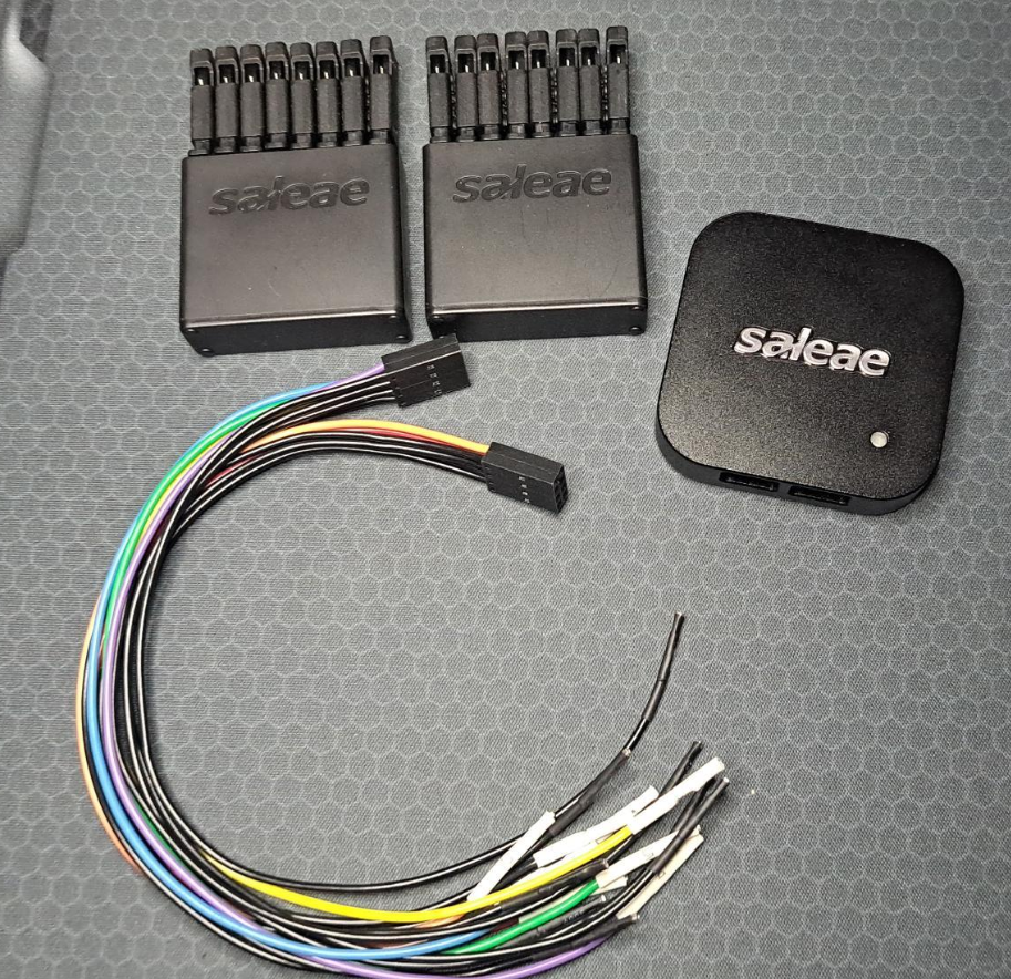
INCLUDED COMPONENTS
• Saleae Logic Pro 8 USB Logic Analyzer, 2x 4
• Channel Wire Harnesses, 16 Micro-Gripper Hooks
• Saleae Carrying Case, USB 3.0 cable
FEATURES
• Deep Sample Buffers
• Highly Portable, USB Attached
• 24 Included Protocol Analyzers
• Automation API
• Custom Protocol Decoder Plugin API
• Edge and Pulse Width Triggering
• Protocol Result Filter and Search
• Measurements, Bookmarks and Timing Markers
• Four Data Export Formats: CSV, Binary, VCD and MATLAB
• Cross Platform Windows, Linux, and OSX
APPLICATIONS
• Firmware Debugging
• FPGA Debugging
• Functional Verification
• Performance Profiling
• Reverse Engineering
• Protocol Decoding
• Data Logging
KEY SPECIFICATIONS
• Eight Digital Channels
• 500 MSPS Digital Sampling (max)
• 100 MHz Max Digital Bandwidth
• Eight Analog Channels
• 50 MSPS Analog Sampling (max)
• 5 MHz Analog Bandwidth
• Recording Length Limited by Available RAM and Density of Recorded Data
• RGB LED, Customizable 24 bit Color
• USB 3.0 Super Speed
Using the Saleae Logic Analyzer
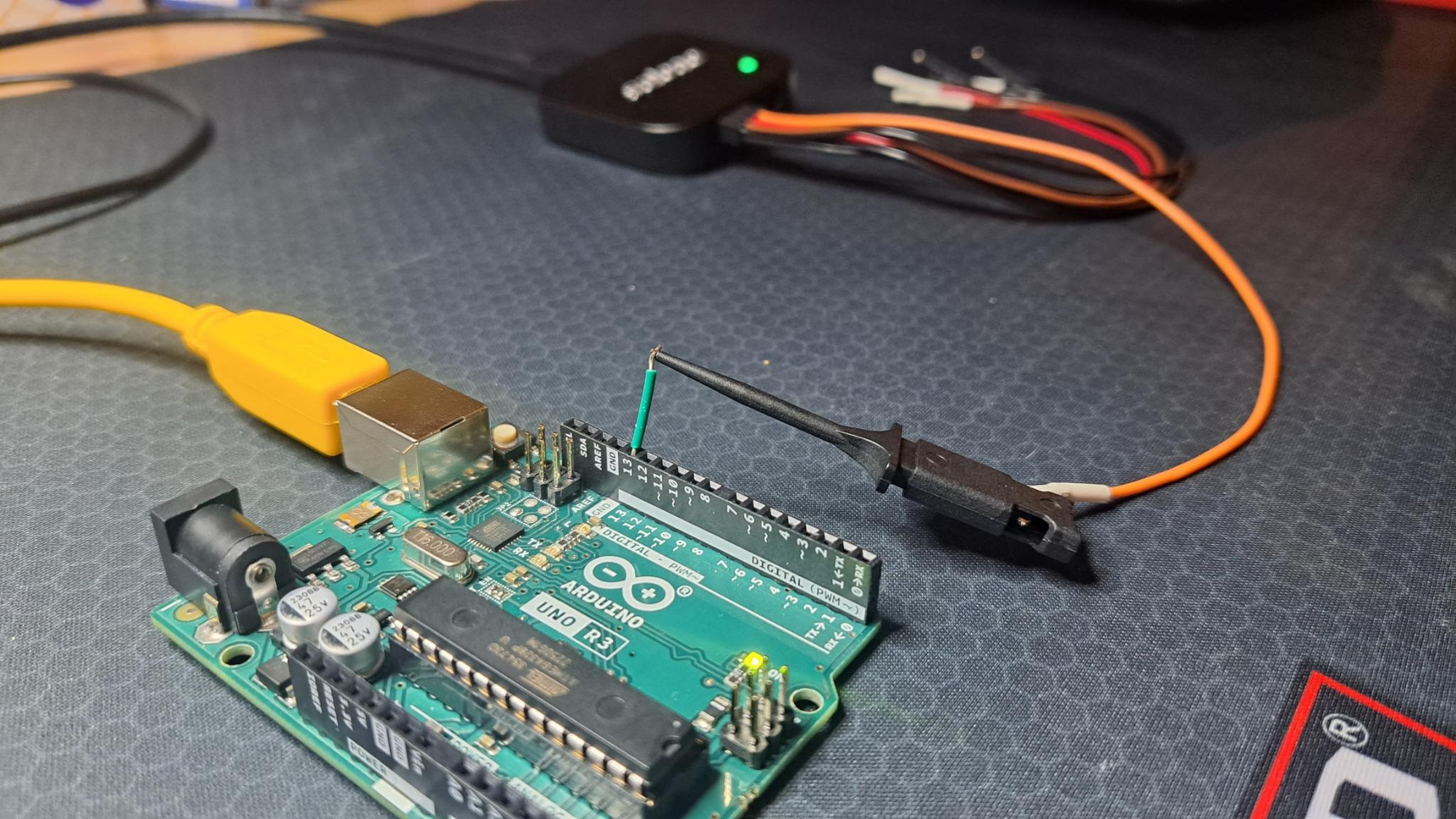
We are going to use the analyzer to read a signal from an Arduino Uno.
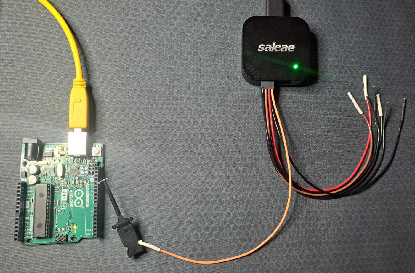
I start by connecting one of the eight channel wire's to the Logic Analyzer, and then onto the 13th Digital Pin on the Arduino Uno using one of the included Probe's.
Afterwards plug both the Saleae Logic Pro 8 and the Arduino Uno into your computer, and install the needed software for the Logic Analyzer to read the signals found here: https://www.saleae.com/downloads/ & the software needed to write the signal coming from the Arduino Uno found at this link here: https://www.arduino.cc/en/software
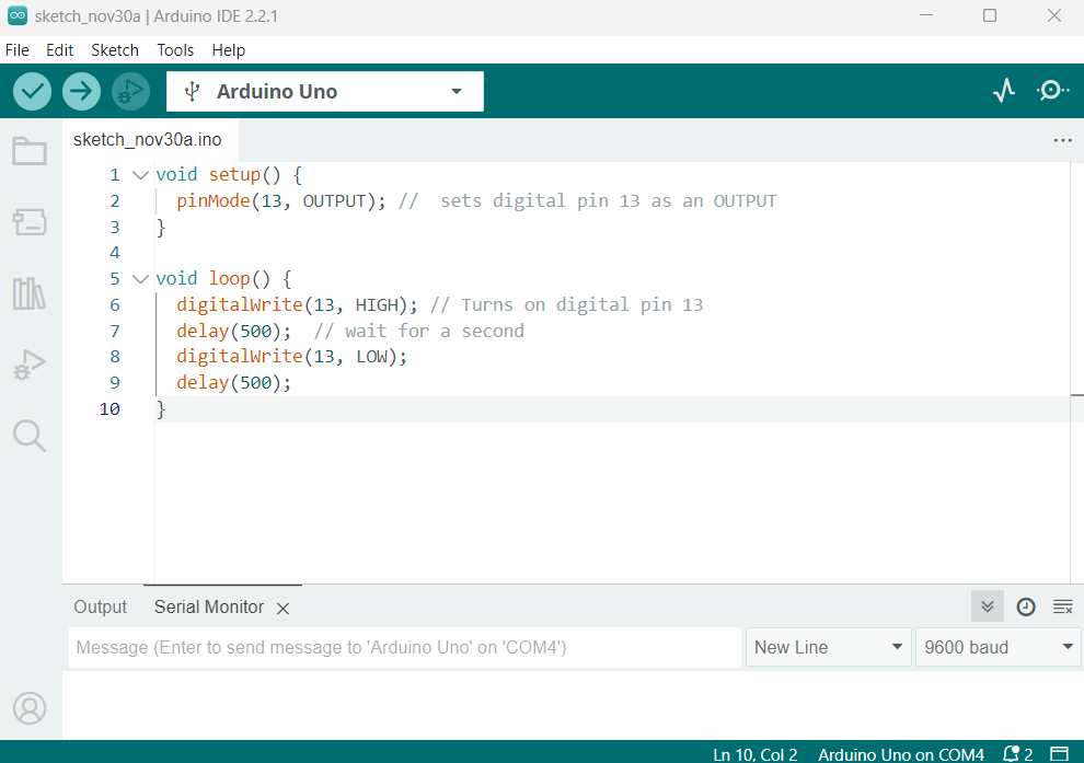
After you're finished downloading, open the Arduino IDE and the following code into the Terminal:
void setup() {
	pinMode(13, OUTPUT);  //  sets digital pin 13 as an OUTPUT
}

void loop() {

	digitalWrite(13, HIGH); // Turns on digital pin 13
 	delay(500);  // wait for a second
 	digitalWrite(13, LOW);
 	delay(500);

}
This is what it looks like in the IDE:
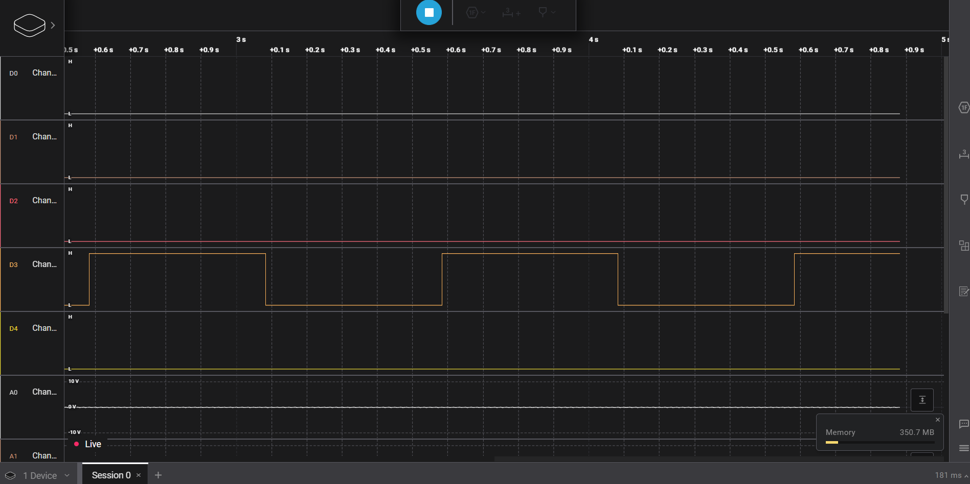
Once finished, both verify and upload your sketch to the Arduino Uno. Then Launch the Logic 2 Logic Analyzer Software and click on the top left icon for Device settings. You'll have to make sure the correct number channel is displayed on the screen below. My probe is plugged into the 4th Channel wire, so the signal being displayed is on the ( D3 ) Channel Sensor.
Decoding a UART signal using the Saleae Pro 8 Logic Analyzer
This time using the Logic Pro 2 Logic Analyzer software, we'll be decoding the signal coming from the Arduino Uno by probing the Rx & Tx, and ground pins.
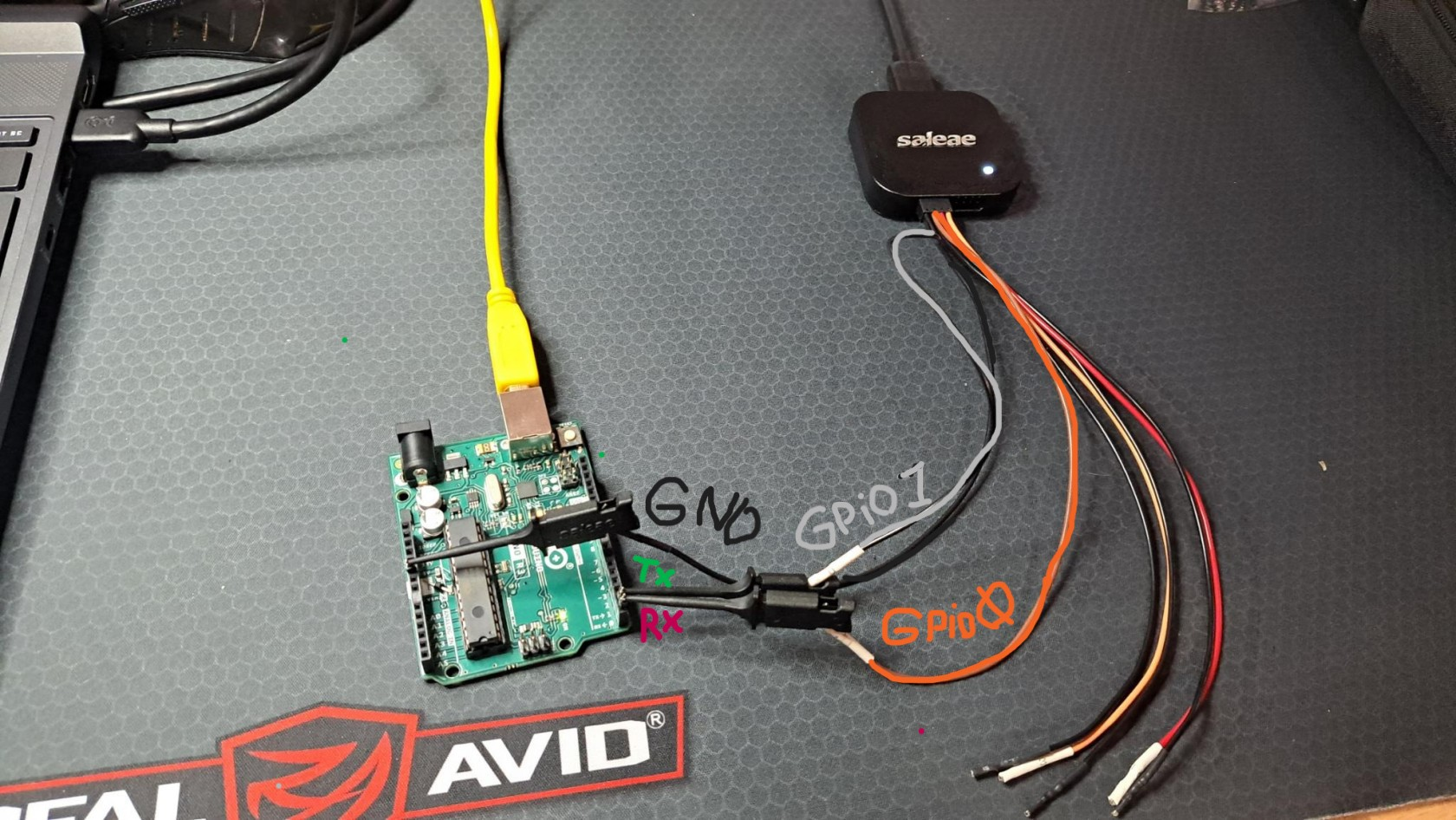
I stared by connecting the two channel probing wires, Channel 0 and Channel 1 to the Tx, and Rx on the Arduino and the ground prob to GRD. I was using some extra male pin headers I had lying around because of the Arduino Uno doesn't actually have any Digital or Analog Male pin headers onboard.
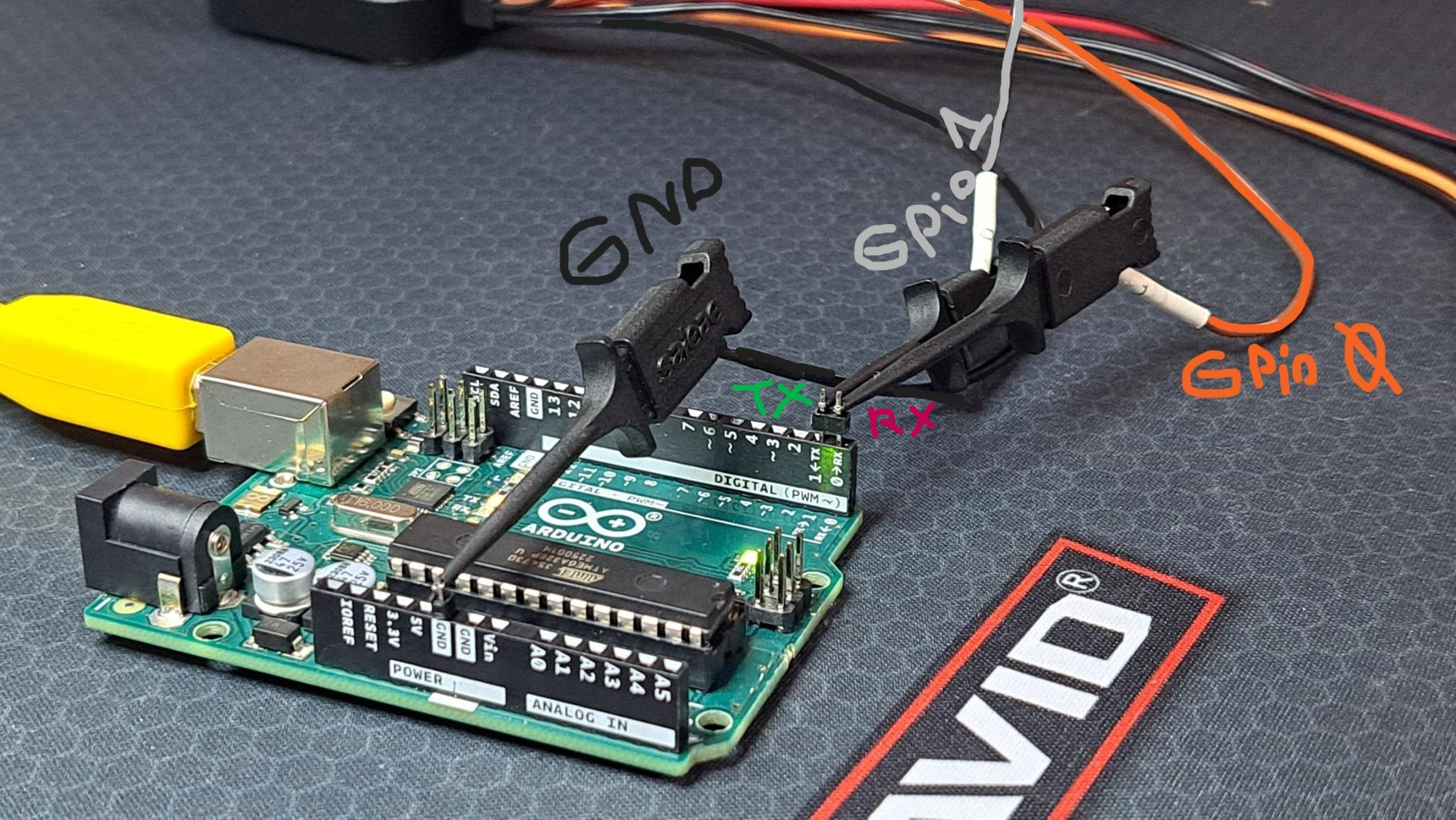
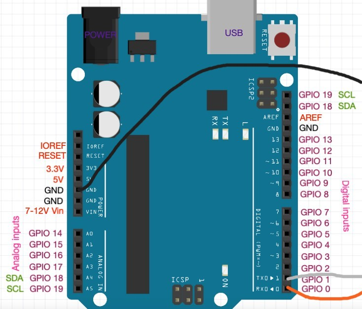
*Here's an available pin-out diagram for reference when attaching the probes: *
Transmitting Arduino the Signal to the Transmit/receive pins
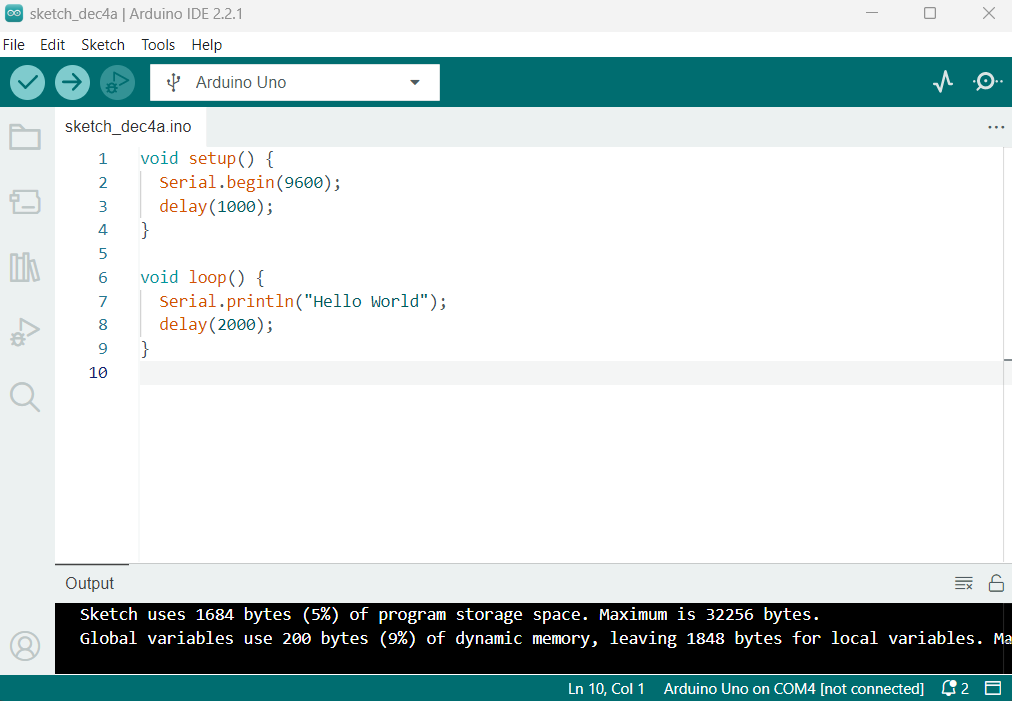
Now we'll be using the Arduino Uno's IDE software to transmit a, "hello" message to the pins so we can probe the signal using the Logic Analyzer. Start by opening up a new sketch in the Arduino IDE software, then proceed to enter this code into the coding window.
void setup() {
	Serial.begin(9600);
    delay(1000);
}

void loop() {
	Serial.println("Hello World");
    delay(2000);
}
And here is a view of the code inside the IDE:
We will be using the " Serial.begin(9600); " function to establish connection between the computer and the Serial Port on the micro-controller.
Then the " Serial.println("Hello World"); " function will print the message to the serial monitor displaying the message "Hello World".
With the " delay(2000): " we'll be telling the Arduino to print the message every 2,000 miliaseconds or 2 seconds.
With the all the code finished, verify & upload the sketch to the Arduino, and launch the Logic Analyzer Pro software. From here we'll be able to use the Logic 2 software to read the signal coming off of the board and translate it to readable text, or Hex, Binary, Decimal, Etc.
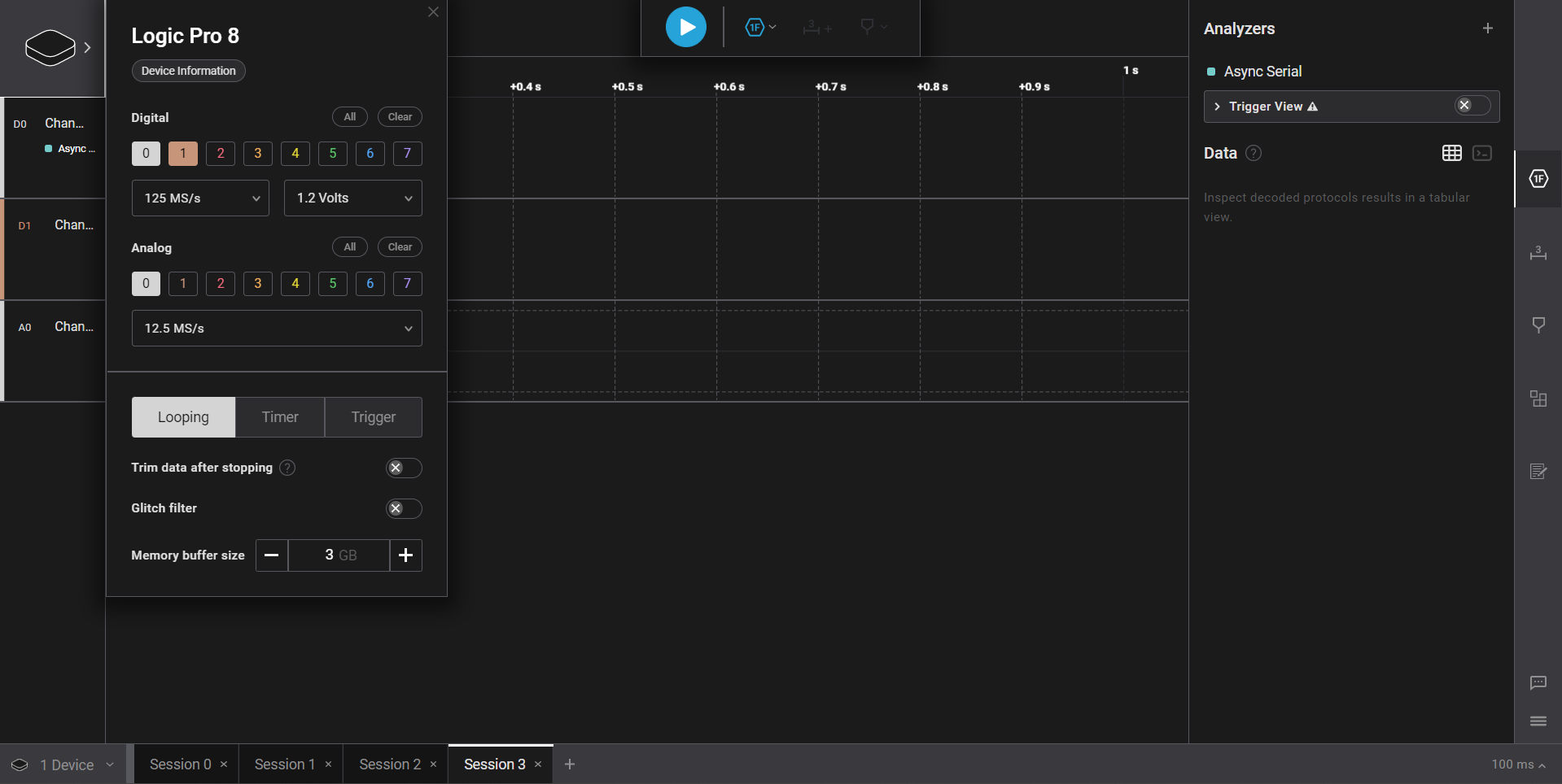
Clicking the Saleae icon on the top left of the screen will allow you to select which or how many channel's your Logic Analyzer will being scanning for. This time I'll just be using Channel 0, & Channel 1 for the Tx, & Rx signals, and the Analog 0 Ground Channel.
Once selected, click the record button at the top of the screen to record the signal coming from the Arduino for a couple of seconds until you see a signal, then pause it.
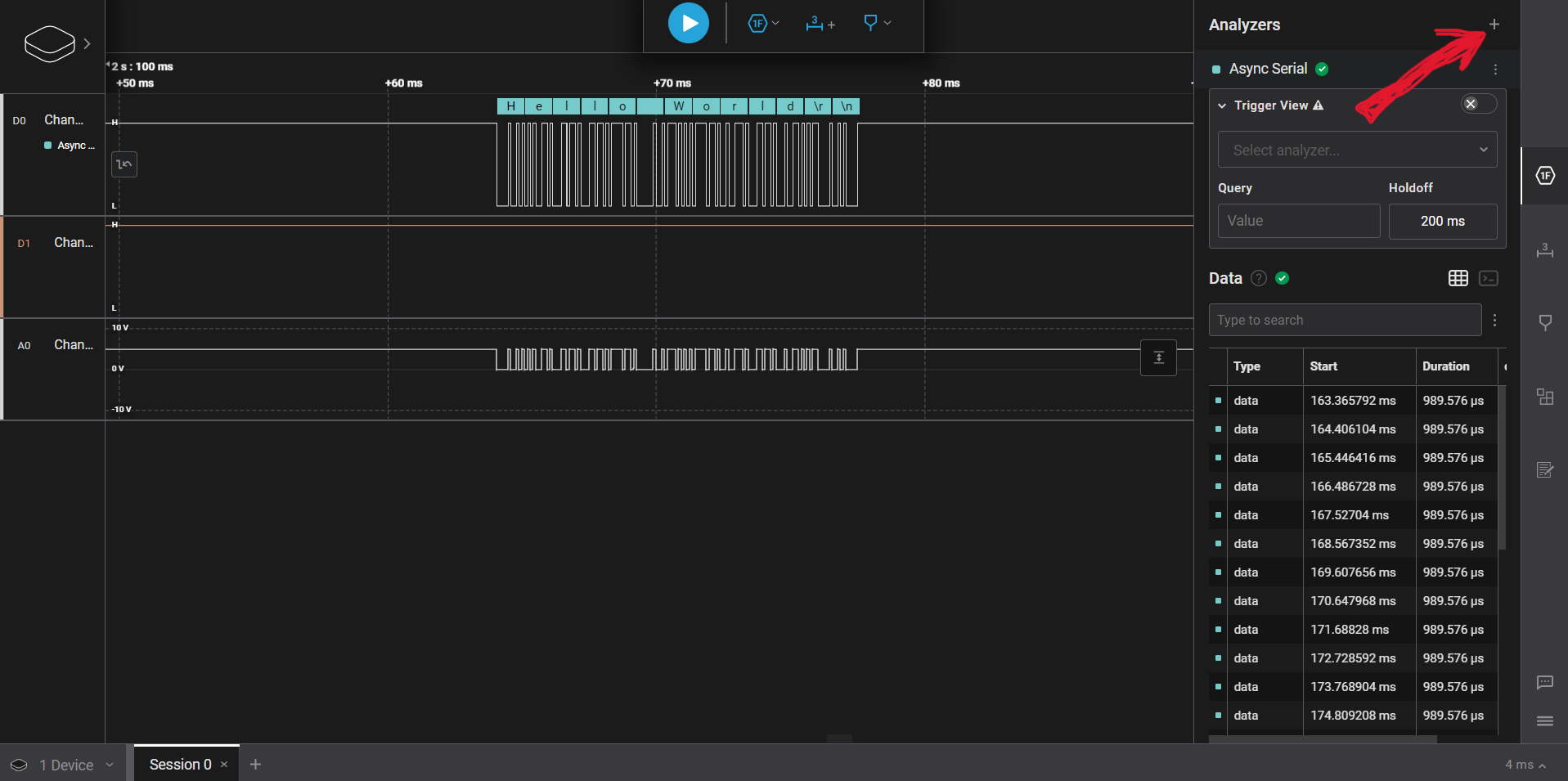
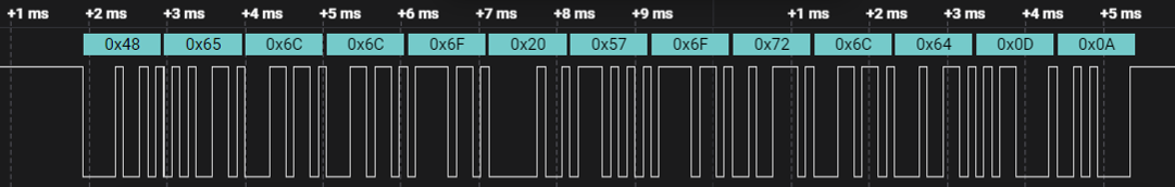
You should see something like this if you zoom into the signal with your scroll wheel. Now go to the right bar of the screen to Analyzer and click the Plus Sign to add a Async Serial Analyzer, (UART) protocol, this will translate each part of the signal into ASCii, Binary, Decimal or Hexadecimal character's.
if Async Serial Analyzer is translating the signal into Hexadecimal numbers you can use a ASCii table translation sheet, as shown here, to manually convert the Hex, Dec, Oct or HTLM code to regular human text. (The manual approach is given to give an opportunity to understand what is happening under the hood.)
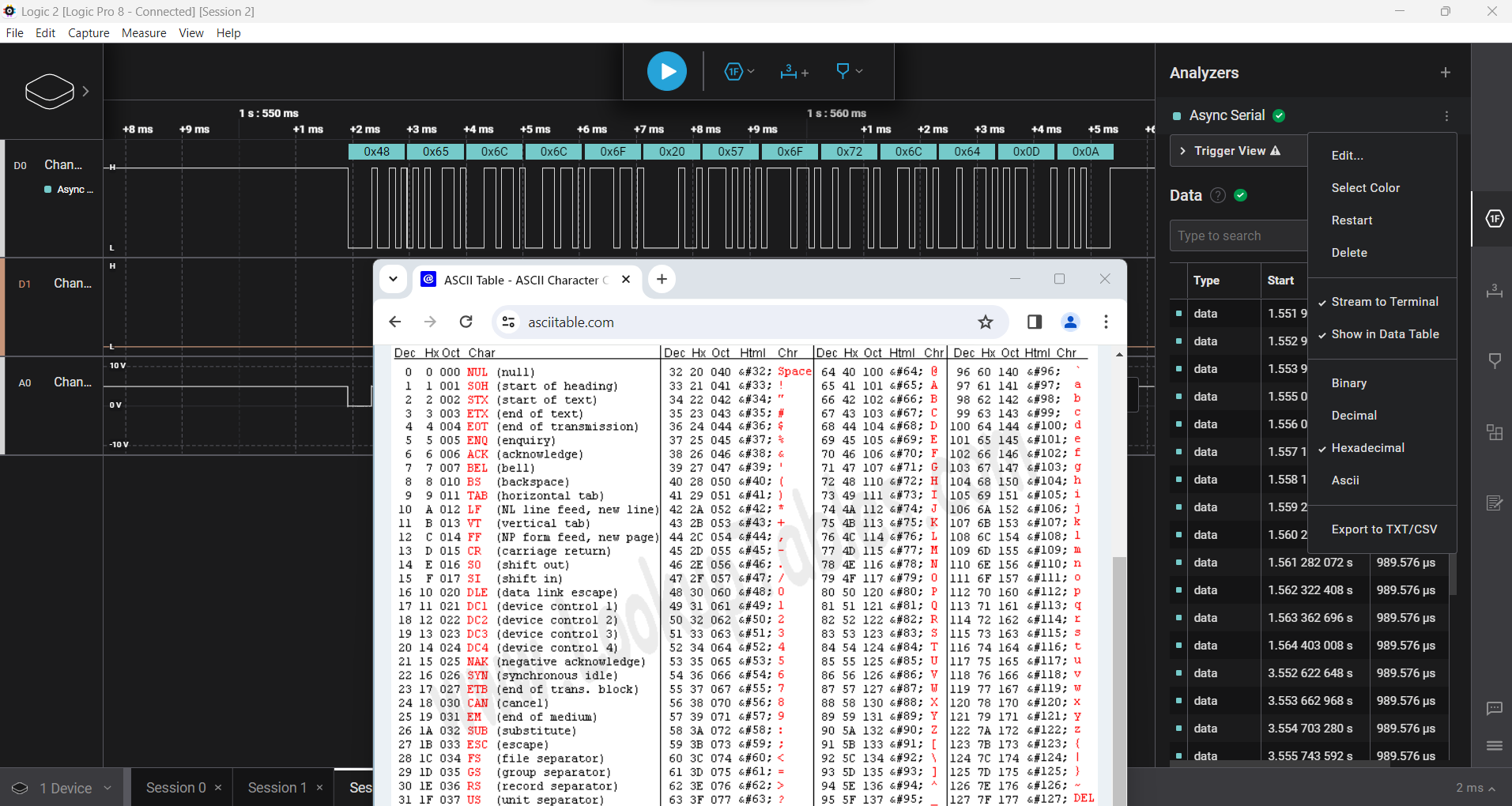
By taking this string of Hex numbers, " 0x48, 0x65, 0x6C 0x6F, 0x20, 0x57, 0x6F, 0x72, 0x6C, 0x64, 0x0D 0x0D " you can formulate the original characters from the Hexadecimal code.
As such, if we were to take a look at that ACii character table and look at each column, we can see that for " 0x48 " the 0, indicates its a Hex number in the first column, but in the third column we can see its number "48", so the English letter is has to be is "H".
Do that for each Hexadecimal letter and you'll eventually get "H" "e" "l" "l" "o" "space" "W" "o" "r" "l" "d".
Hello World
*The last two numbers in the string "0x0D" & "0x0D" or in English, " \r " and " \n " are representing a "newline" character or an enter character. these can ignored for this example.
Thanks,
Matt