
What I Am Doing - Part 1 Hardware Reversing


I thought I'd give a little peak into Red Crow labs. We have quite a bit of gear for analyzing and reverse engineering hardware so I'll show some of it in use today. I'm using a Raspberry Pi 4 for this because its easy and because I can't show any photos of customer equipment due to NDAs.
Today I'm walking through the process of identifying UART pins on a device, analyzing them a little bit, and then accessing the firmware via UART.
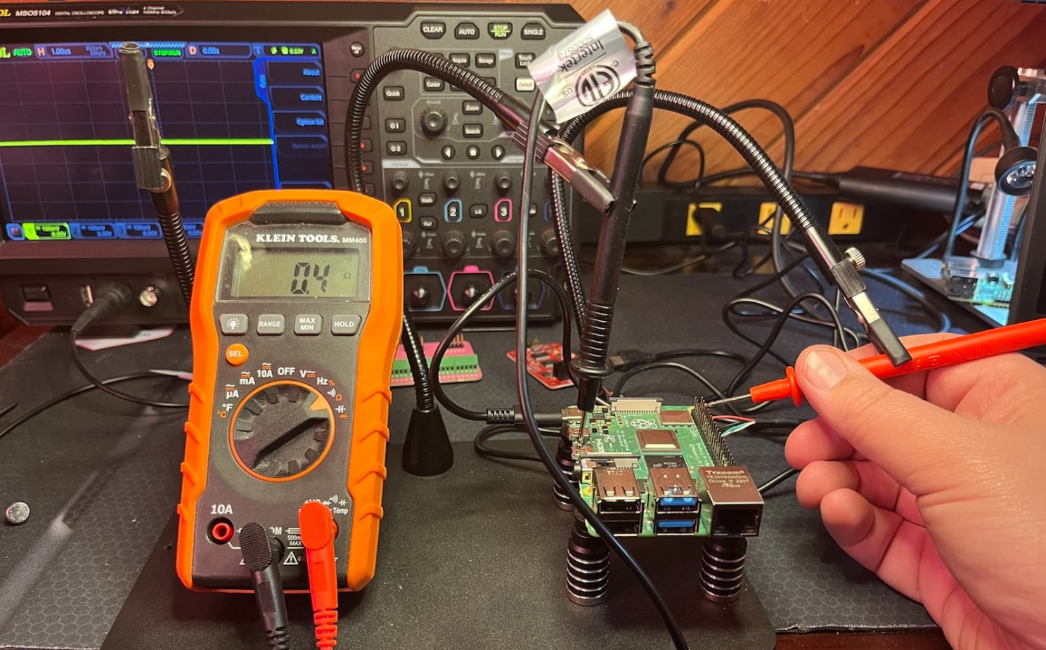

On the raspi there is a whole pile of pins to choose from for potential targets. The first thing we do is identify a ground pin by connecting the multimeter in continuity mode to a grounded part of board, in this case one of the HDMI connectors, and then touching the red probe to pins until we get a beep / continuity reading.
NOTE: you have to set enable_uart=1 in the /boot/config.txt file on the raspi so that the pins are active.
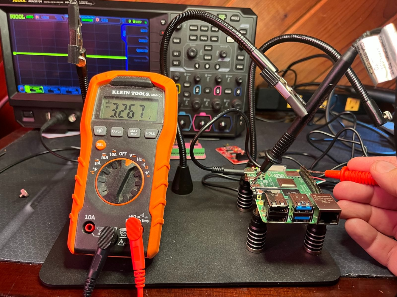

Next we touch the probe until we find a pin with variable voltage that is a likely candidate for TX. The first two pins are 5 and 3 volts for power which we don't need. The third pin is ground and the forth pin doesn't have signal so could be RX. The fifth pin has variable voltage.
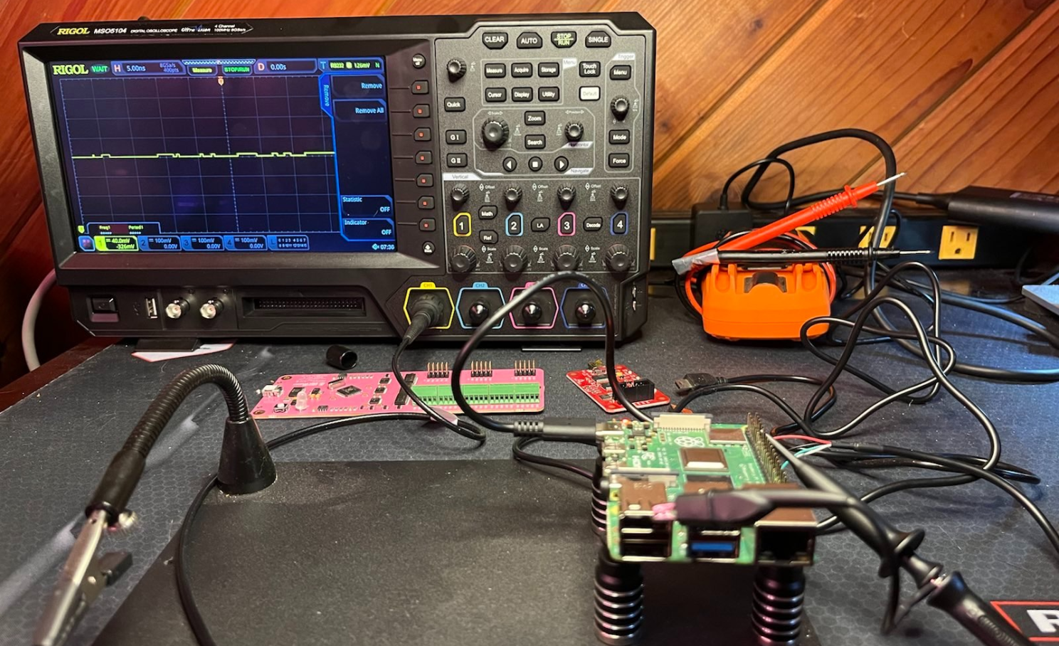

Next we attach the Oscilloscope Channel 1 to the identified TX pin and a ground and reboot the raspi to see the signal. (There is a bit of calibration on the oscilloscope that is needed, setting it to RS232, setting a trigger, etc.)
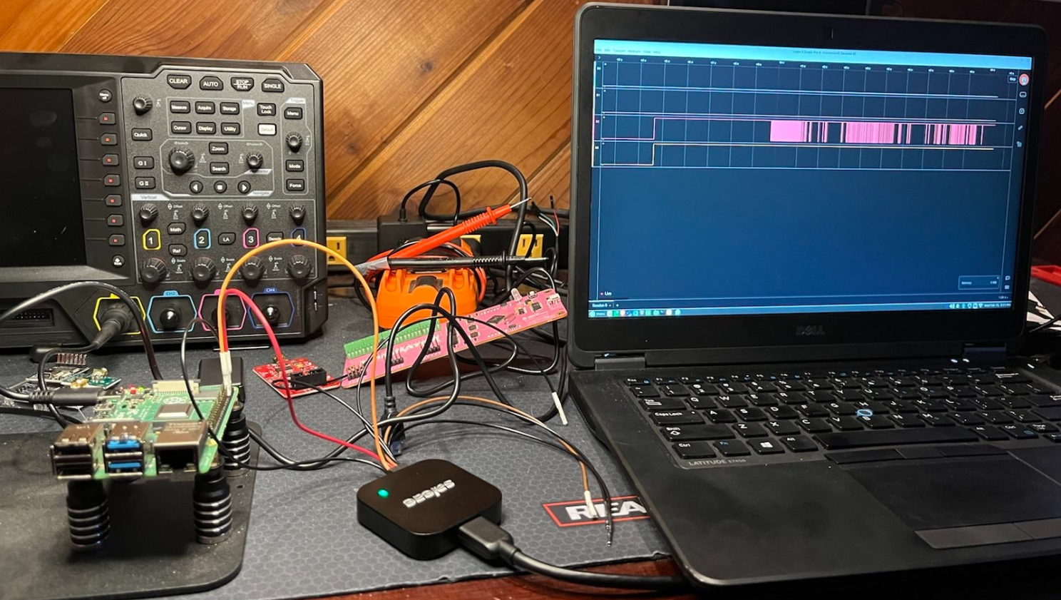

Now we hook up a logic analyzer and boot the device. The leads are connected to the ground, RX and TX pins and you can see the boot up signal which we can analyze more deeply, but it looks like we have identified the right pins. You can spot our JTAGulator and BusPirate in the background that we will use in a later post.
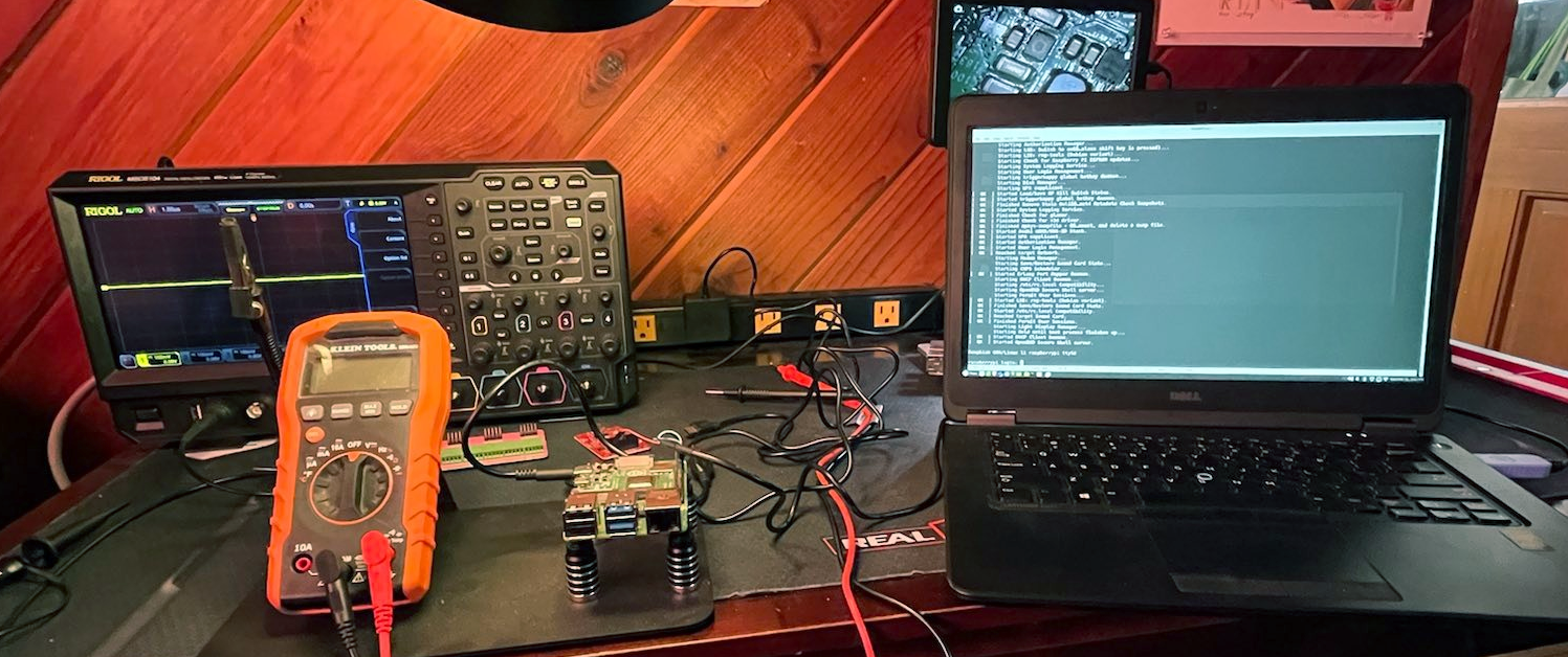

Next we connect a USB to TTL Serial Cable from AdaFruit Industries that has the SiLabs CP2012 chipset. Now we can snoop on all the boot messages and even get to a login shell prompt on the device. There is quite a bit of software setup to make all these things work but this post is getting long so we will leave that for another day.

Lab cat is not amused that I haven't dumped and reverse engineered the firmware yet, but that's coming soon.
Thanks for your attention,
A.