
What I Am Doing - Part 2 UART Analysis

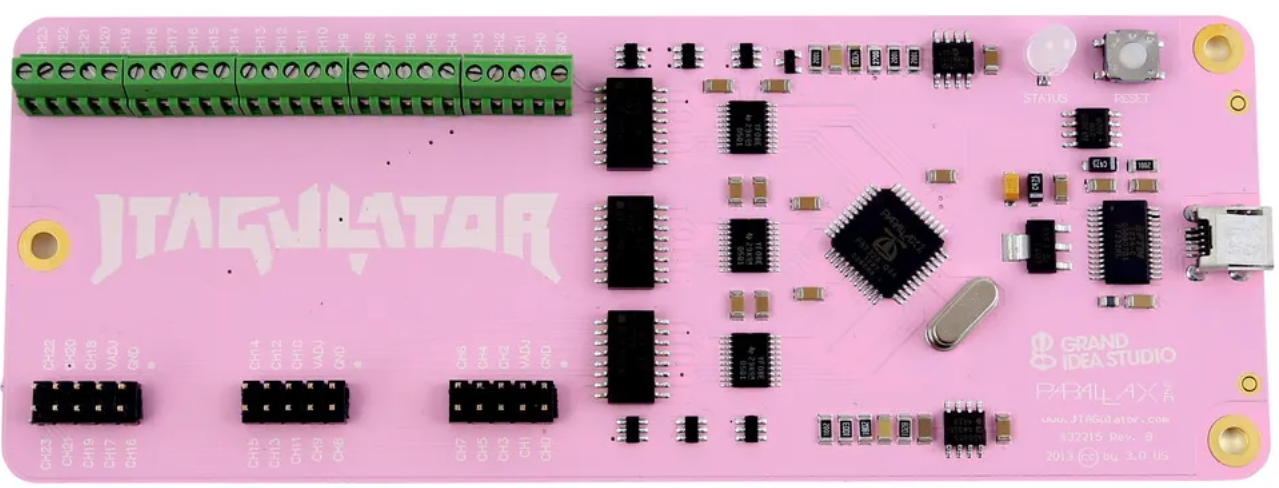
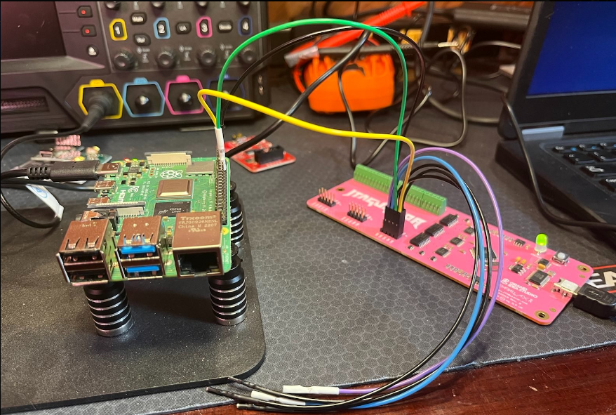
Today I'm playing with a jtagulator device on the same setup as the last article. I have it wired up to the GPIO pins on the raspi that correspond to the UART (I'm cheating a little since I figured out what the pins were last time), and I have it connected to my analysis laptop running Linux. First we wire up the raspi to the jtagulator:

Next, we double check to make sure the jtagulator is being seen by the OS:
root@rftao:~# lsusb
Bus 002 Device 008: ID 0403:6001 Future Technology Devices International, Ltd FT232 USB-Serial (UART) IC
Next we check dmesg to try to figure out what TTY it's connected to:
root@rftao:~# dmesg
[244830.646726] usb 2-2: New USB device found, idVendor=0403, idProduct=6001, bcdDevice= 6.00
[244830.646740] usb 2-2: Product: FT232R USB UART
[244830.652596] usb 2-2: FTDI USB Serial Device converter now attached to ttyUSB0
I snipped some of the info to keep this short, but we can see its connected to ttyUSB0.
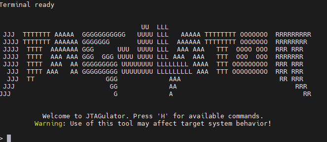
You can use whatever terminal program you like, but I'm using picocom so we setup the connection to the jtagulator:
root@rftao:~# picocom /dev/ttyUSB0 -b 115200

Next we setup the voltage for the device by hitting V and then entering 3.3. The raspi 4 is 3.3v. Then we bruteforce the pins. We already know these from the previous article but we will use the jtagulator to figure it out anyway:
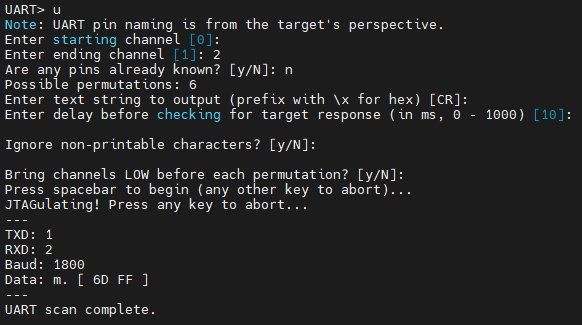

This identifies the transmit and receive pins for us as well as the baud rate. I'm not sure why it says 1800 as I know it is 115200 but I'm ignoring that for now. Now we do a UART passthrough and attempt to watch the raspi boot through the jtagulator:
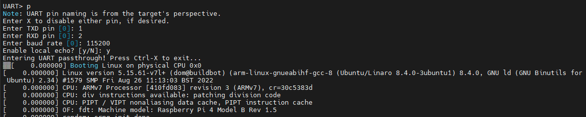

So far so good, we can see the entire boot process coming from the raspi. I'll do another article about dumping the firmware as that's a longer topic. However, I asked chatGPT for a python script to help in extracting the firmware and this is what it gave me in about 1 second:
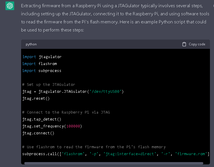

I haven't tested this code out, but it has the interface right and the general flashrom command for dumping.
Next we take a look at the dump file, determine its type, look for useful strings:
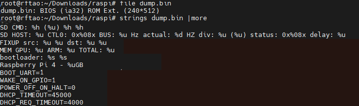

I cut out a number of lines to make the image a reasonable size but we can see hints about the architecture, device, and even some of the device config options. Then we do a hexdump using xxd and have a look around. I also edited the lines in this image:
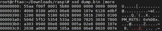

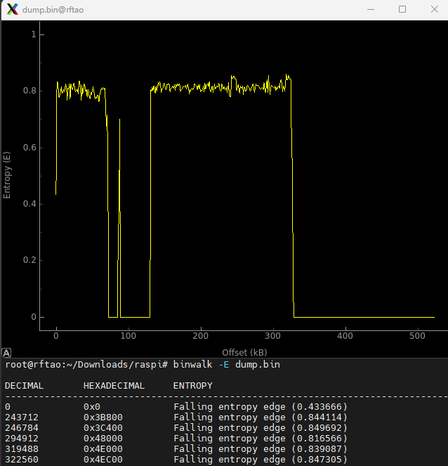
We can see another hint, PM_RSTS which is a Broadcom chip register used in Raspberry Pi's. Next we take a look at the entropy of the firmware file which will give us some hints about its structure, compression, etc.:

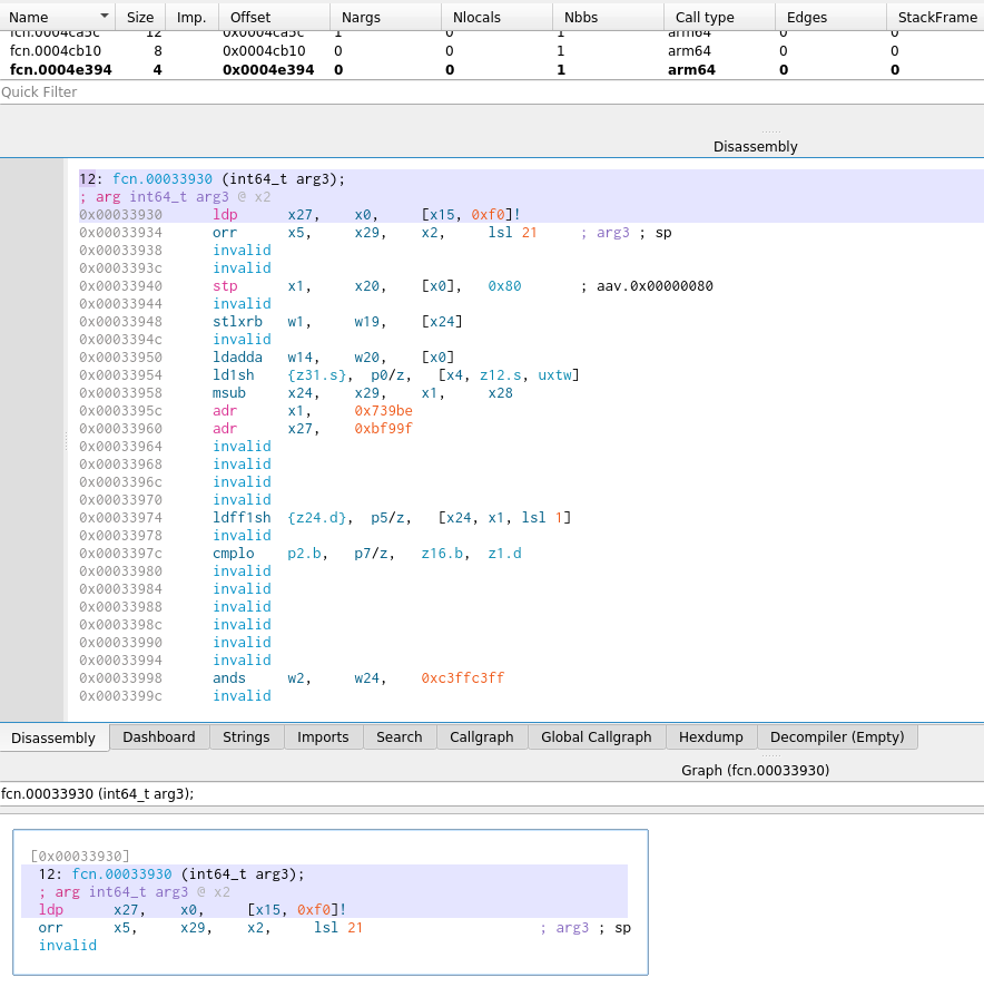
IDA Pro doesn't quite know how to open the dump, so will need some tweaks and extraction first. Just for the heck of it I opened the dump in radare2's Iaito, setting the architecture to ARM, and get a little bit of potentially useful information.

I'll leave it there for now, but this gives you a little view into Red Crow labs basic hardware analysis process.
Thanks for listening,
A.